

MINY / PRODUCTS
BLOW MOLDING
IBM 135H servo injection blow molding machine for 15-1500 mL containers. 70 mm screw and 1500 kN injection clamping force. Request a quote.
PRODUCT / IBM-135H
IBM 135H Electro-Hydraulic Injection Blow Molding Machine
IBM 135H is an electro-hydraulic servo injection blow molding machine for 15-1500 mL containers. It combines a 70 mm screw with 1500 kN injection mold clamping force for small-bottle production.
- Drive system
- Electro-hydraulic servo
- Container volume
- 15-1500 mL
- Screw diameter
- 70 mm
- Injection clamping force
- 1500 kN
- Dry cycle
- 3 s
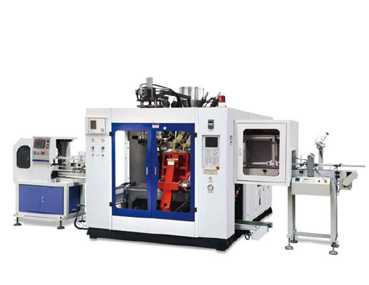
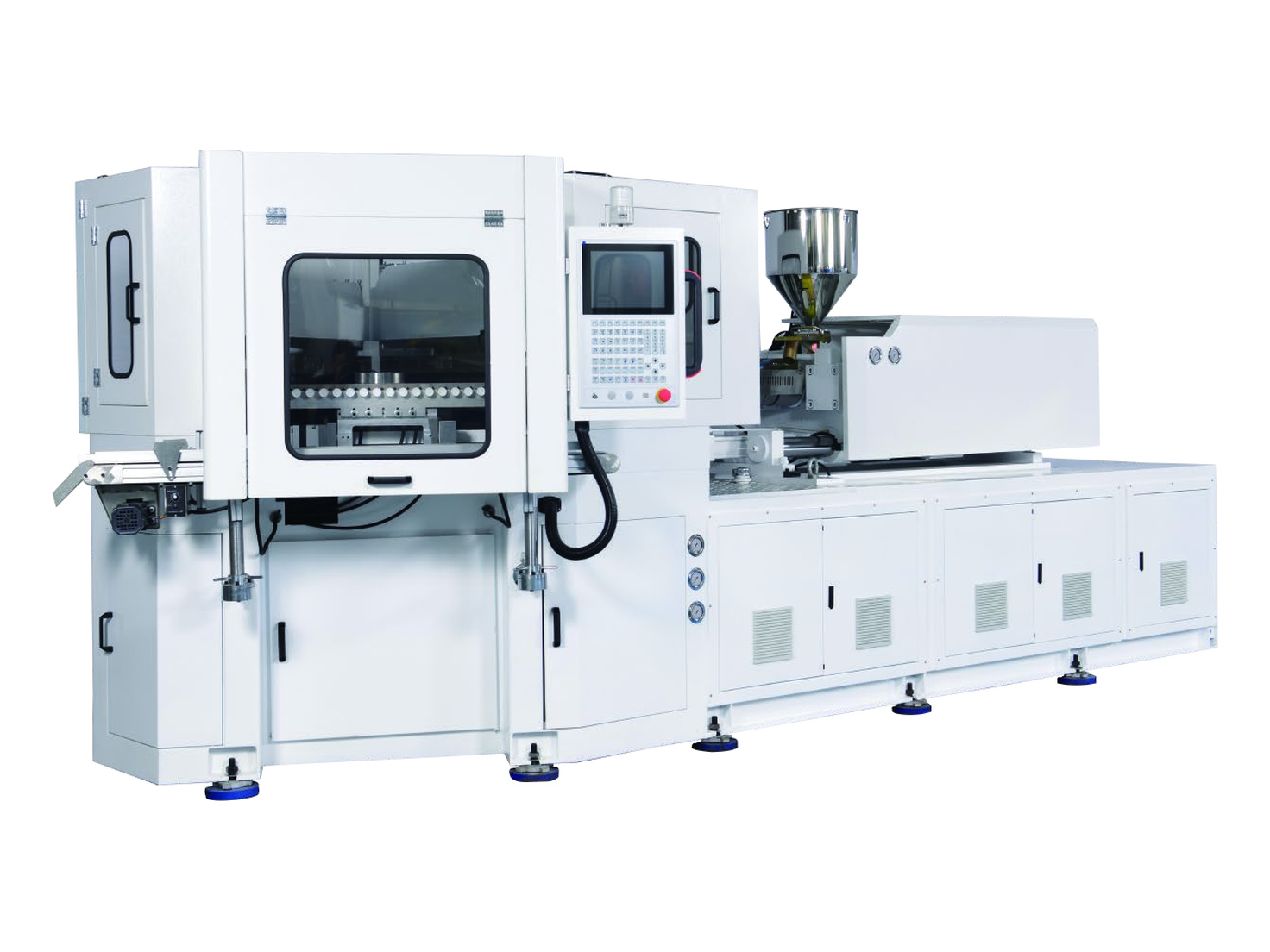
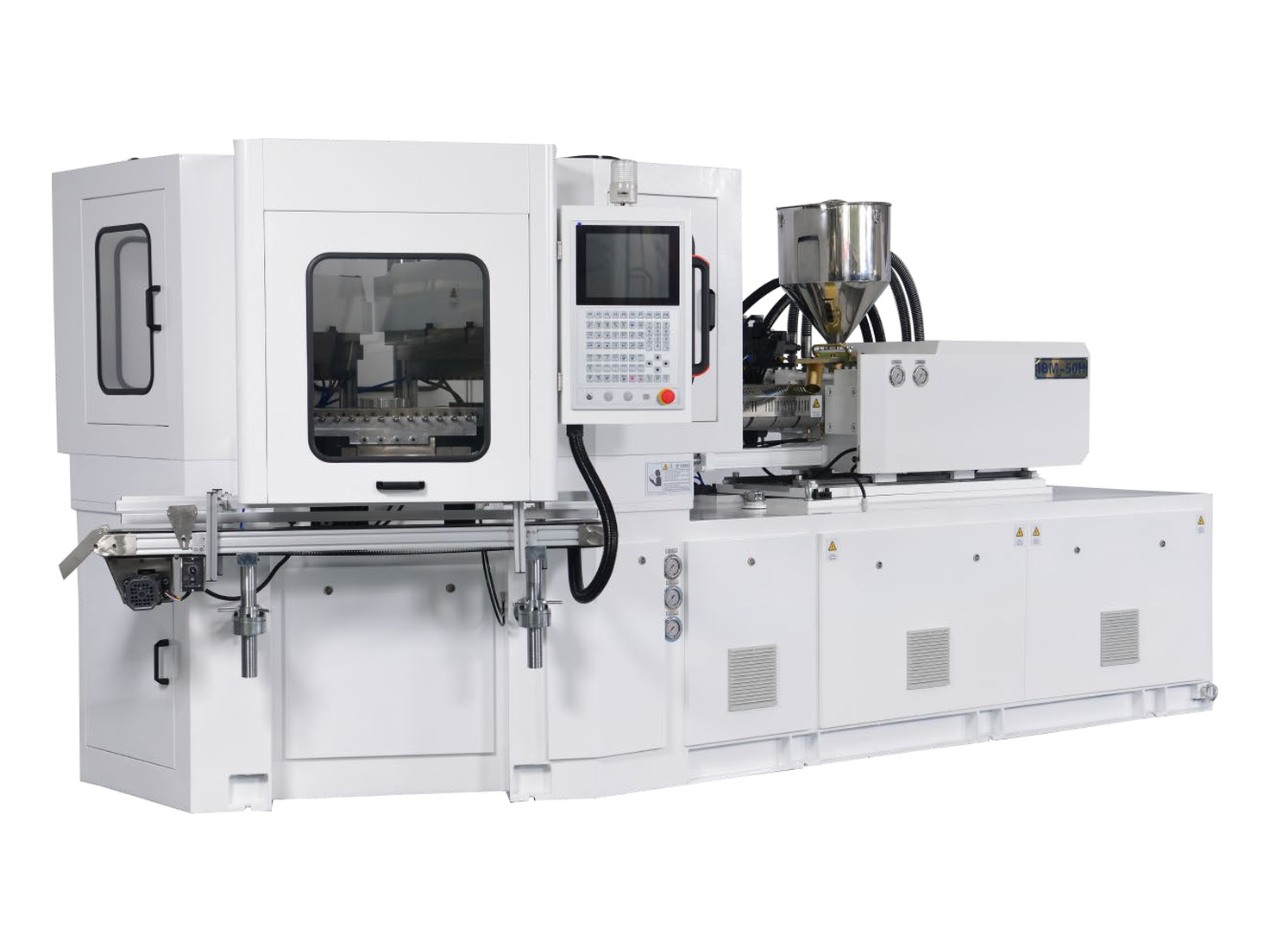
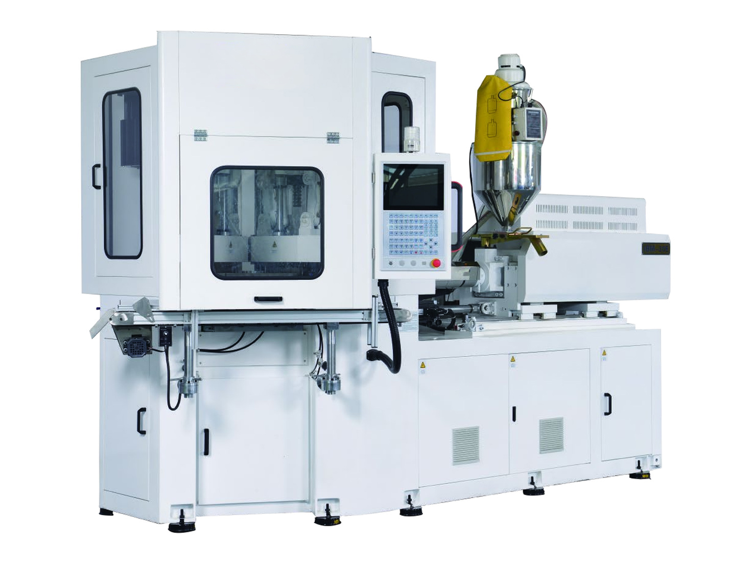
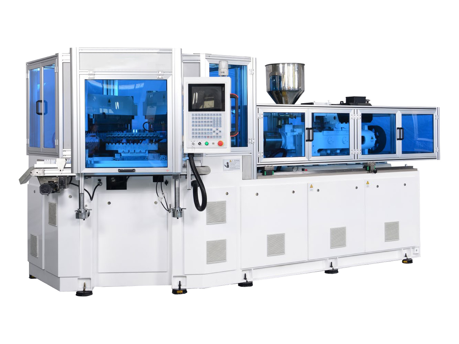
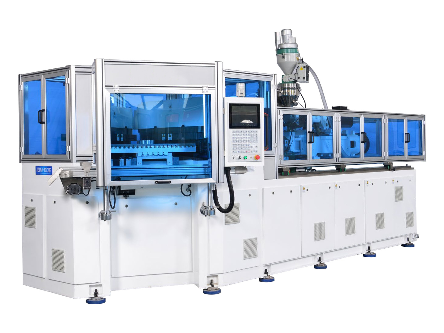
H-series reference image from the catalogue; appearance may vary by model.
PRODUCT DETAILS
Product Overview
IBM 135H integrates injection molding, blow molding and bottle take-off in a rotary production process. Bottle geometry, resin and mold configuration determine the final production setup.
Applications
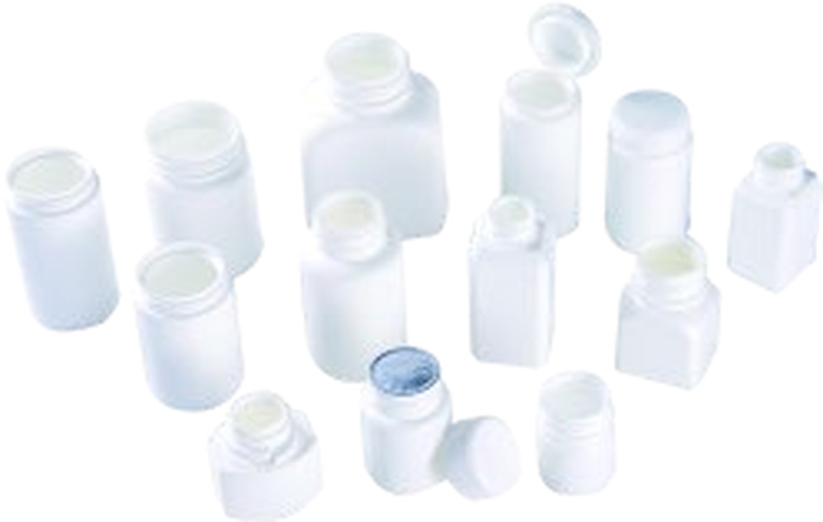
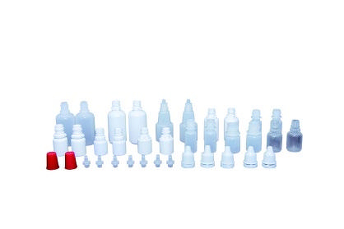
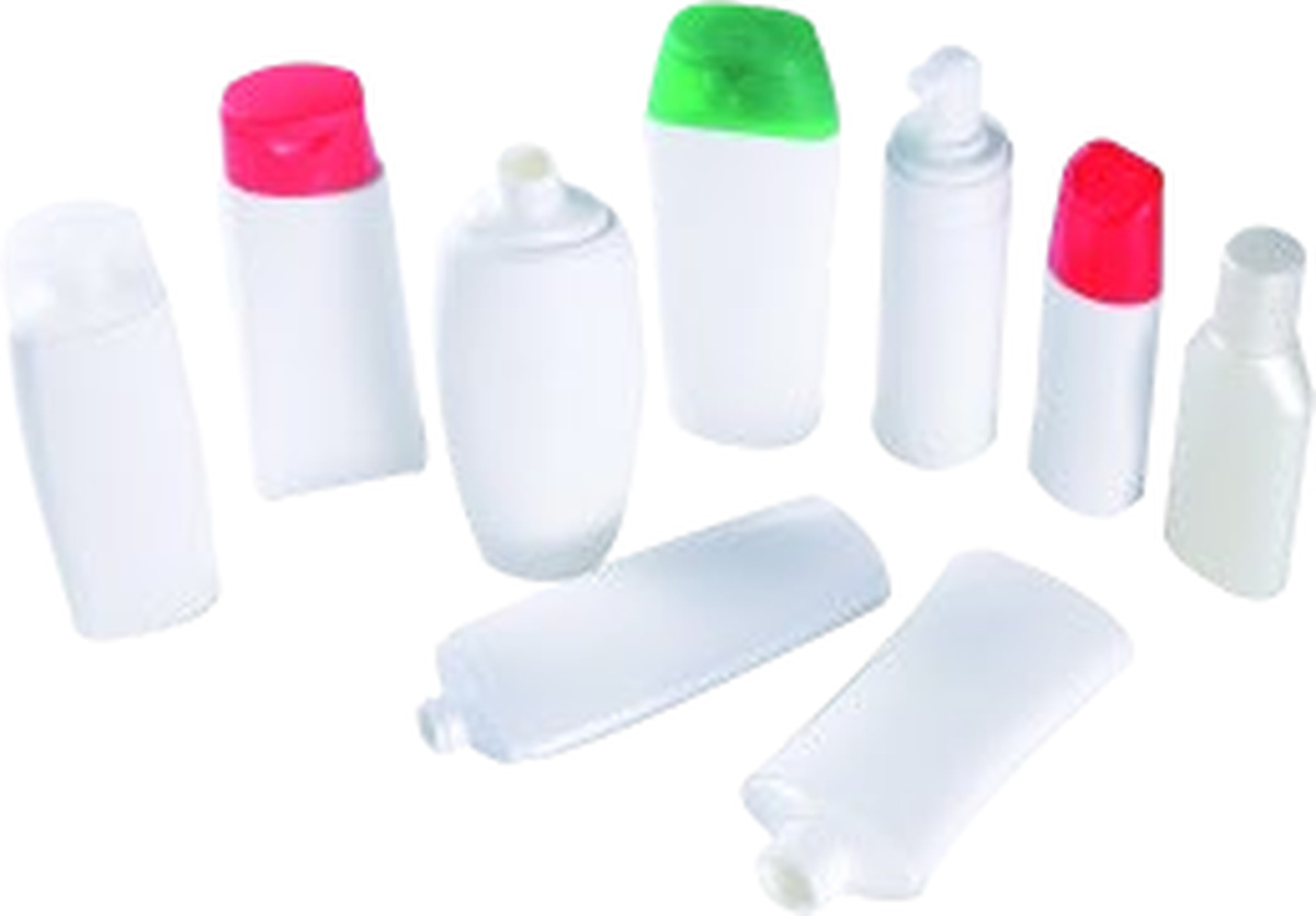
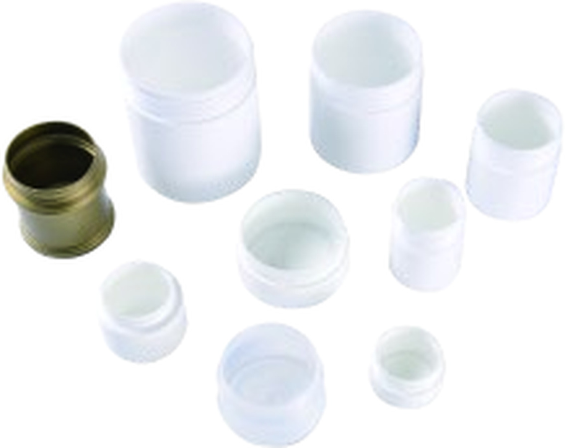
Typical catalogue applications include pharmaceutical bottles, eye-drop containers, cosmetic packaging, food containers and wide-mouth jars. The examples below show application types; bottle dimensions and mold requirements must match the selected machine.
Injection Blow Molding Features
- Injection and blow molding are integrated in one machine, with rotary transfer through injection, blowing and bottle take-off stations.
- Accurately molded bottle necks and threads support a range of closure and sealing designs.
- Smooth parting lines and controlled bottle geometry support consistent surface appearance.
- Multi-cavity molds accommodate different bottle sizes; tooling is selected for the required bottle and output.
- Bottle weight, wall thickness and volume can be controlled through the preform and mold design.
- An accessible mold area supports tooling changes and production changeovers.
- The catalogue lists HDPE, LDPE, PE, PP, PS and EVA applications; select the resin and tooling for the intended container.
Electro-Hydraulic Servo System
- An electro-hydraulic hybrid servo system coordinates motor output, hydraulic flow and pressure with machine demand.
- A servo motor drives rotary-table movement for repeatable transfer between molding stations.
- Double beams, four tie bars and a clamping cylinder below the rotary table provide space for mold movement.
- Auxiliary cylinders handle mold opening and closing, while the main clamping arrangement applies balanced locking force.
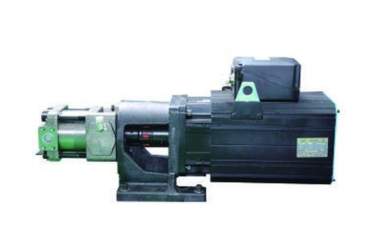
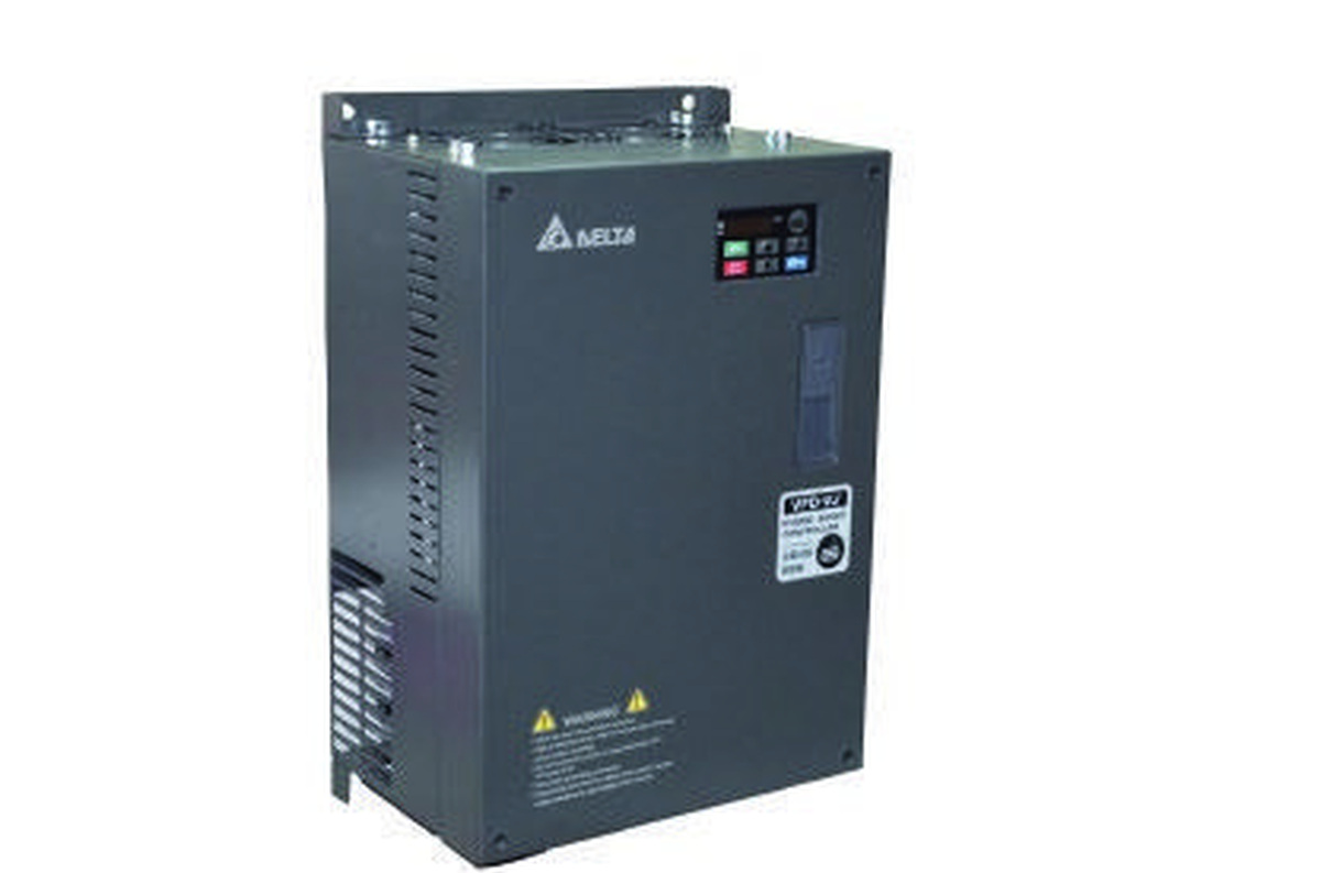
- The hydraulic assembly combines a servo motor, servo drive, pump and precision control interface.
- Digitally controlled melt backpressure supports convenient and repeatable process adjustment.
The catalogue cites an energy-saving reference of 40%. Compare energy use under the intended bottle, resin, mold and operating conditions.
Technical Specifications
| Parameter | Unit | IBM 135H |
|---|---|---|
| Screw diameter | mm | 70 |
| Screw L/D ratio | — | 22 |
| Maximum injection volume | cm³ | 1153 |
| Maximum injection weight (HDPE / PS) | g | 1000/1210 |
| Maximum injection pressure | MPa | 158 |
| Maximum screw stroke | mm | 272 |
| Screw speed | rpm | 175 |
| Barrel heating power | kW | 19 |
| Heating zones | — | 5 |
| Injection mold clamping force | kN | 1500 |
| Blow mold clamping force | kN | 247 |
| Mold opening stroke | mm | 140 |
| Rotary-table lifting height | mm | 75 |
| Maximum mold platen size (L × W) | mm | 1140 × 500 |
| Minimum mold thickness (±0.05 mm) | mm | 280 |
| Mold heating power | kW | 8 |
| Ejection stroke | mm | 240 |
| Main servo motor power | kW | 75 |
| Hydraulic system pressure | MPa | 14 |
| Product volume | L | 0.015-1.5 |
| Maximum product height | mm | ≤285 |
| Maximum product diameter | mm | ≤120 |
| Dry cycle | s | 3 |
| Compressed-air pressure | MPa | 1.2 |
| Compressed-air flow rate | m³/min | ≥0.8 |
| Cooling-water flow rate | m³/h | 3.5 |
| Machine dimensions (L × W × H) | m | 6.5 × 2.7 × 2.4 |
| Machine net weight | t | 18 |
| Total rated power | kW | 164 |
Dry-cycle values describe unloaded machine movement. The production cycle depends on the container, resin, mold and process settings.
Mold Cavity Reference
| Bottle volume (mL) | Reference cavity count |
|---|---|
| 15 | 18 |
| 20 | 16 |
| 40 | 16 |
| 60 | 14 |
| 100 | 11 |
| 120 | 10 |
| 200 | 8 |
Indicative catalogue examples only. Final cavity count depends on bottle design, material and mold configuration; confirm tooling for the intended container.
Related
Products.
VIEW ALL PRODUCTS 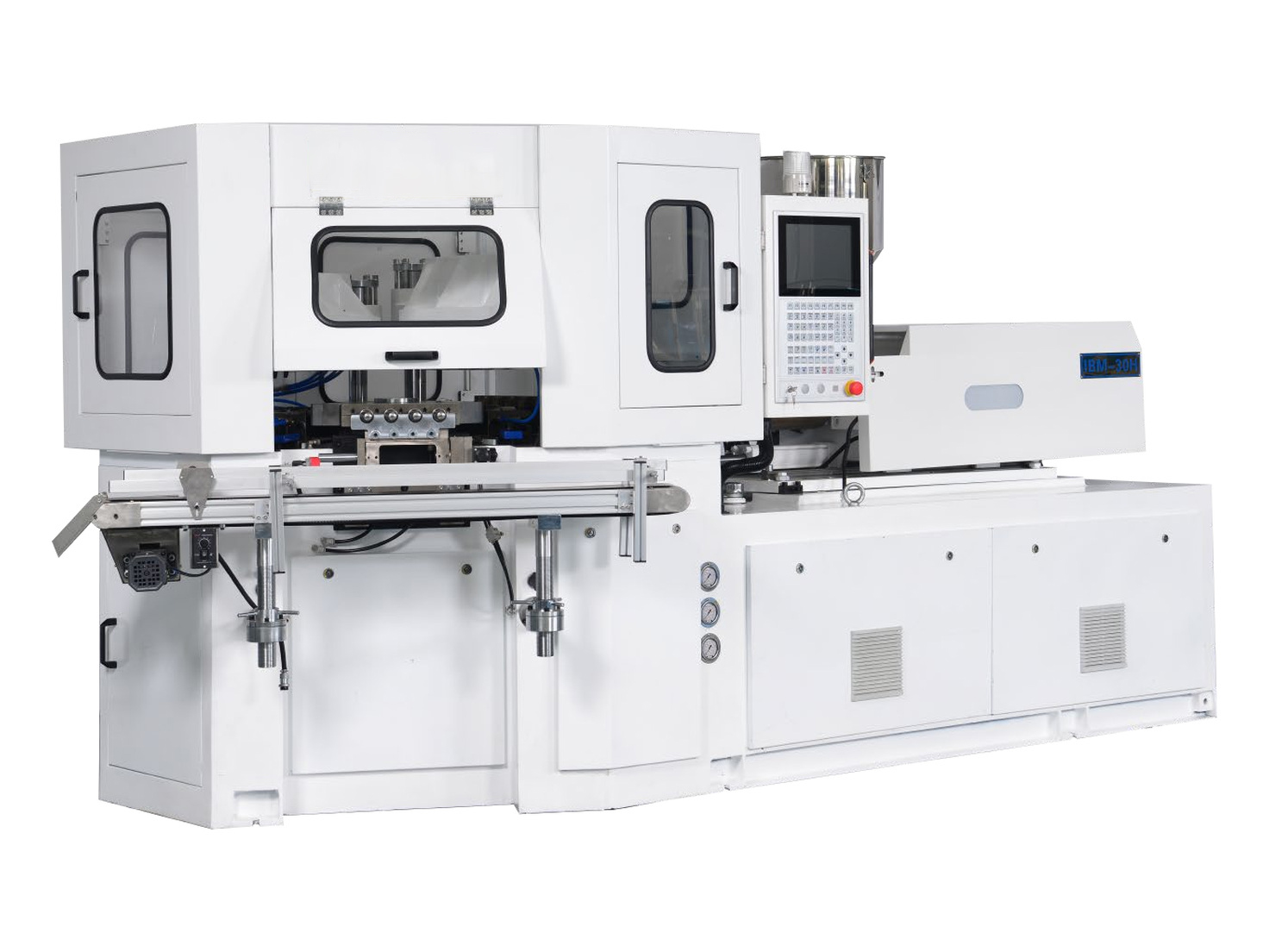
START A CONVERSATION
Tell us what
you are planning
to produce.
Share your product, output and production requirements. Our team will help you find the right configuration.