

MINY / PRODUCTS
BLOW MOLDING
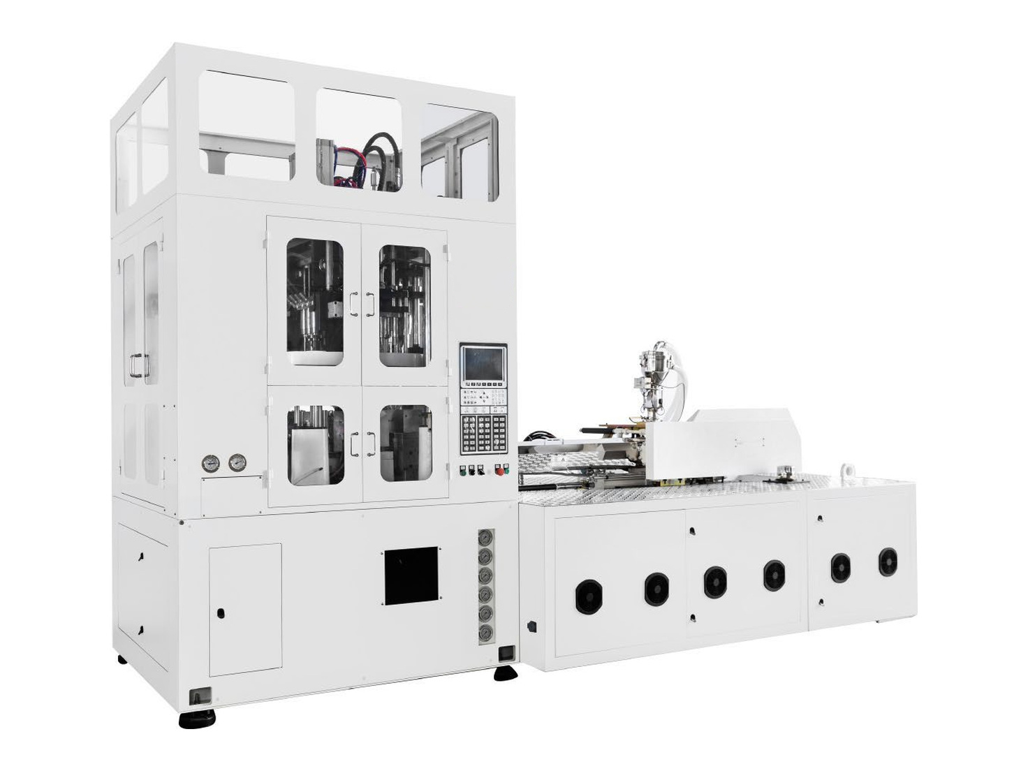
BPET-125V4 single-stage injection stretch blow molding machine for bottles up to 5L. Four stations and a 60 mm screw. Compare cavity options and get a quote.
PRODUCT / BPET-125V4
BPET-125V4 Single-Stage Injection Stretch Blow Molding Machine
BPET-125V4 is a four-station, single-stage injection stretch blow molding machine. The catalogue lists bottle configurations up to 5L and tooling arrangements from 1 to 12 cavities, with the permitted bottle size depending on cavity count.
- Molding process
- Single-stage injection stretch blow molding
- Workstations
- 4
- Maximum bottle volume
- 5L (tooling dependent)
- Tooling configurations
- 1-12 cavities
- Screw diameter
- 60 mm
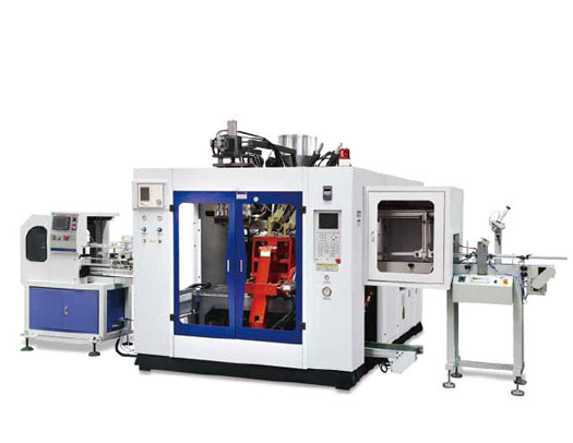
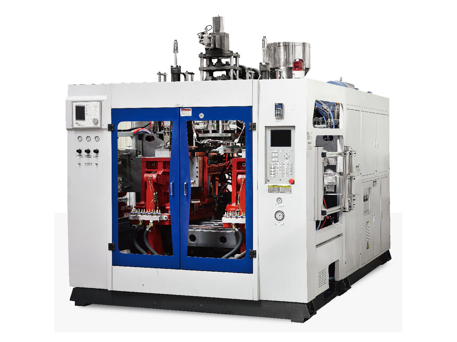
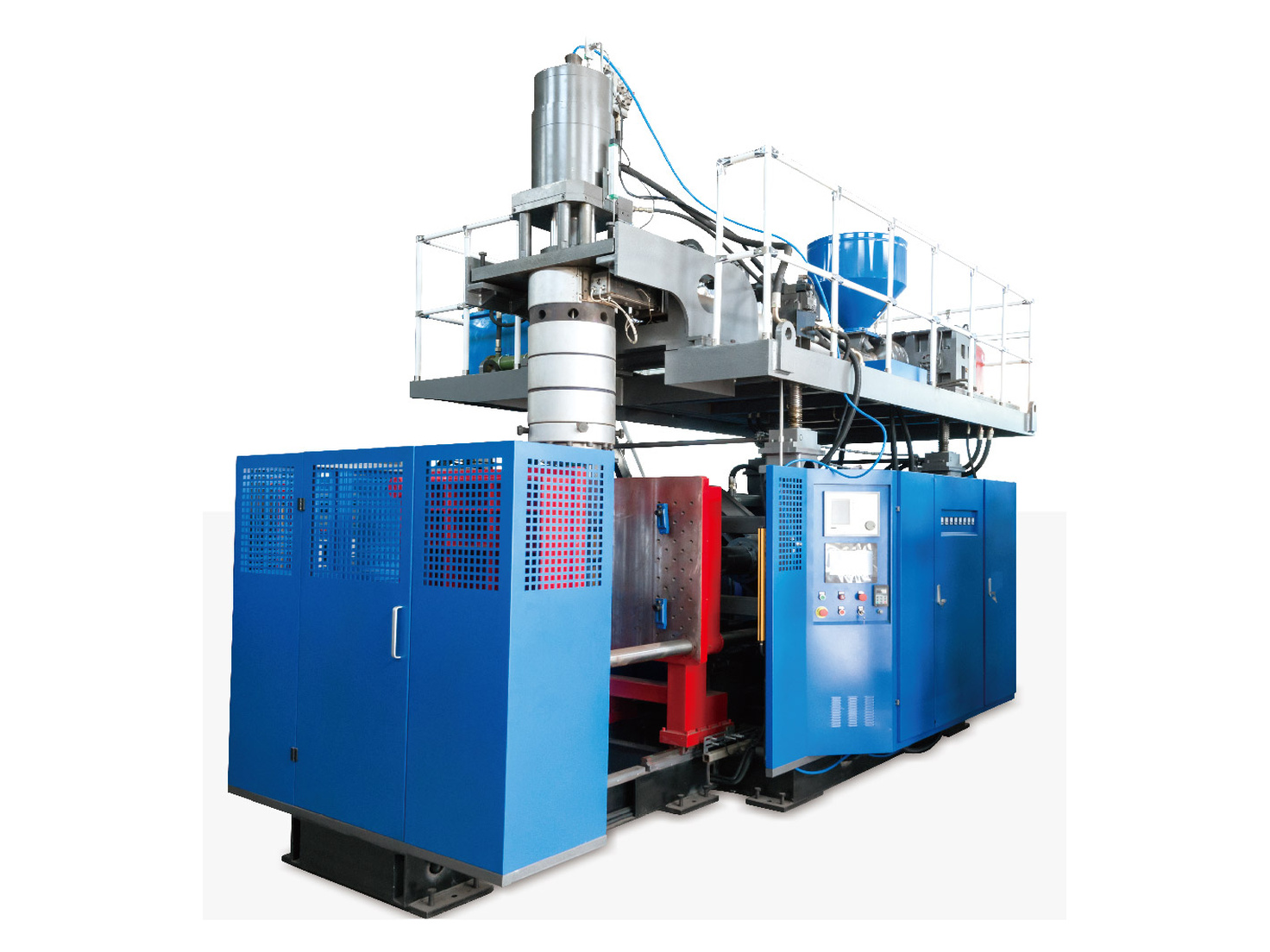
BPET series reference image from the catalogue; model-specific appearance may vary.
PRODUCT DETAILS
Product Overview
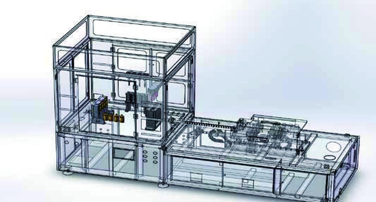
Injection molding, preform conditioning, stretch blowing and bottle take-out are integrated in one machine. The four-station layout transfers the preform between stages without a separate preform-reheating production line.
Applications
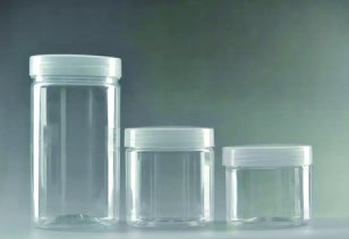
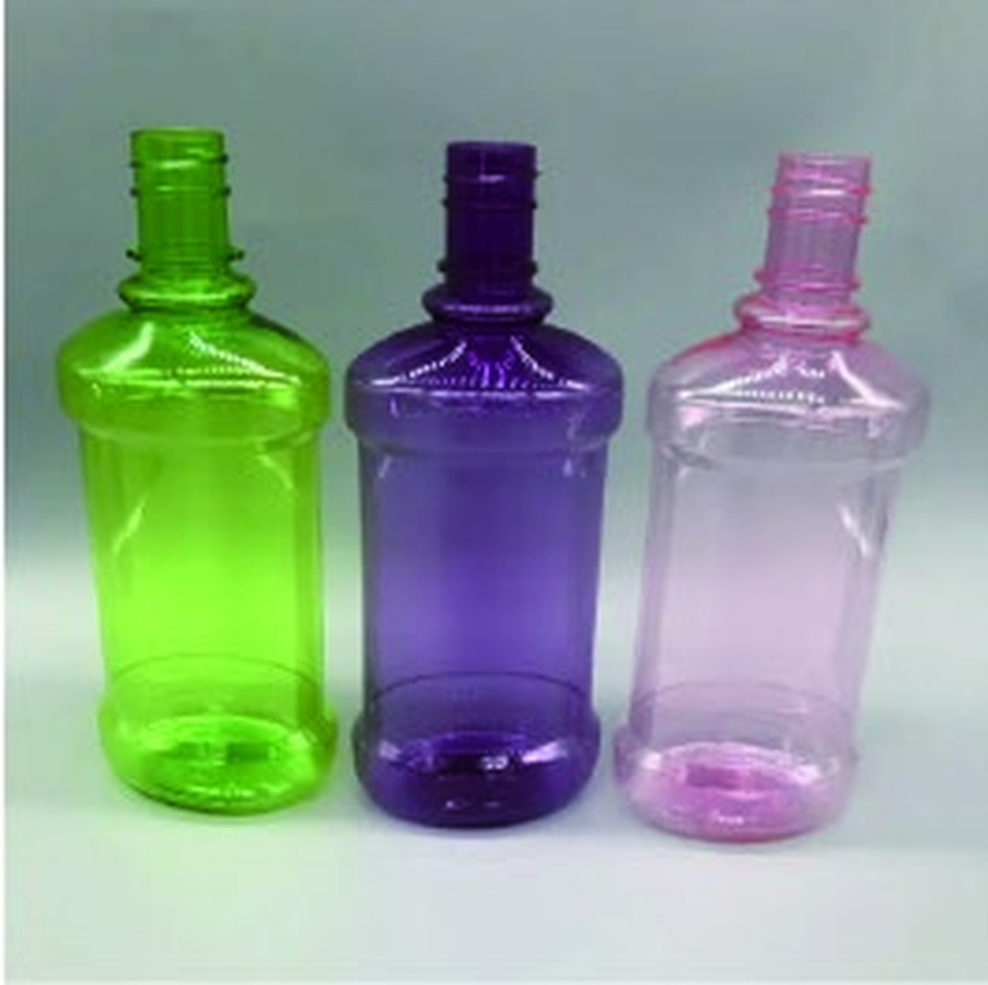
Catalogue examples include cosmetic packaging, personal-care bottles, wide-mouth jars and shaped transparent containers. Bottle size and shape must fit the selected cavity configuration.


Single-Stage ISBM Features
- Integrated injection and stretch blow molding supports production from resin to finished containers in one machine.
- Preform and bottle tooling can be matched to the required neck finish, container shape and production target.
- The four-station arrangement includes preform conditioning and pre-blowing before stretch blowing.
- Integrated processing reduces intermediate handling and supports clean container production.
- The catalogue lists PET, PETG, transparent PP, SAN, PC, PS, PMMA and Tritan applications. Confirm resin and tooling for the intended container.
- The equipment is described with both injection blow molding and injection stretch blow molding capability, subject to the selected tooling and process.
The catalogue cites a 45% energy-saving reference for the BPET series. Compare consumption using the intended resin, container, mold and production setup.
Four-Station Process
| Station | Process |
|---|---|
| 1 | Injection molding |
| 2 | Preform conditioning, tail trimming and pre-blowing |
| 3 | Stretch blow molding |
| 4 | Bottle take-out |
Technical Specifications
| Parameter | Unit | BPET-125V4 |
|---|---|---|
| Screw diameter | mm | 60 |
| Screw L/D ratio | — | 25 |
| Theoretical injection volume | cm³ | 520 |
| Injection mold clamping force | kN | 685 |
| Blow mold clamping force | kN | 286 |
| Chilled-water flow rate | L/min | 80 |
| Cooling-tower water flow rate | L/min | 200 |
| Rated drive power / voltage | — | 65 kW / 380 V |
| Rated heater power / voltage | — | 12.5 kW / 220 V |
| Oil tank capacity | L | 640 |
| Machine dimensions (L × W × H) | mm | 5300 × 2100 × 3100 |
| Machine weight | t | 11.6 |
| Maximum blow-air pressure | MPa | 3.5 |
| Machine running air pressure | MPa | 1 |
Bottle Size and Mold Cavity Reference
Capacity and cavity count are linked. The largest bottle volume and the maximum number of cavities are separate configurations.
| Cavities | Center distance (mm) | Max. neck diameter (mm) | Max. body diameter (mm) | Max. height (mm) | Max. volume (mL) |
|---|---|---|---|---|---|
| 1 | — | 148 | 204 | 300 | 5000 |
| 2 | 310 | 120 | 152 | 300 | 3000 |
| 3 | 170 | 99 | 130 | 300 | 2000 |
| 4 | 135 | 94 | 120 | 300 | 1000 |
| 5 | 105 | 73 | 98 | 300 | 800 |
| 6 | 85 | 57 | 78 | 250 | 600 |
| 7 | 72 | 42 | 66 | 250 | 450 |
| 8 | 60 | 36 | 54 | 250 | 400 |
| 9 | 58 | 34 | 53 | 250 | 300 |
| 10 | 50 | 26 | 44 | 250 | 250 |
| 11 | 46 | 23 | 40 | 250 | 200 |
| 12 | 44 | 18 | 37 | 250 | 100 |
Catalogue reference values. A dash indicates that center-to-center spacing does not apply to the single-cavity configuration. Confirm the final bottle design and mold configuration before ordering.
Typical Production Line
The catalogue layout shows the molding machine with air supply, cooling, mold-temperature control and bottle take-out equipment. Auxiliary equipment is configured for the production line.
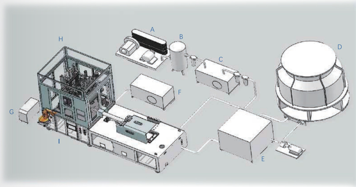
| Layout reference | Equipment |
|---|---|
| A | High-pressure air compressor |
| B | Air receiver tank |
| C | Refrigerated air dryer / filter |
| D | Cooling tower |
| E | Chiller |
| F | Low-pressure air compressor |
| G | Mold temperature controller |
| H | ISBM machine |
| I | Mechanical take-out arm |
Related
Products.
VIEW ALL PRODUCTS 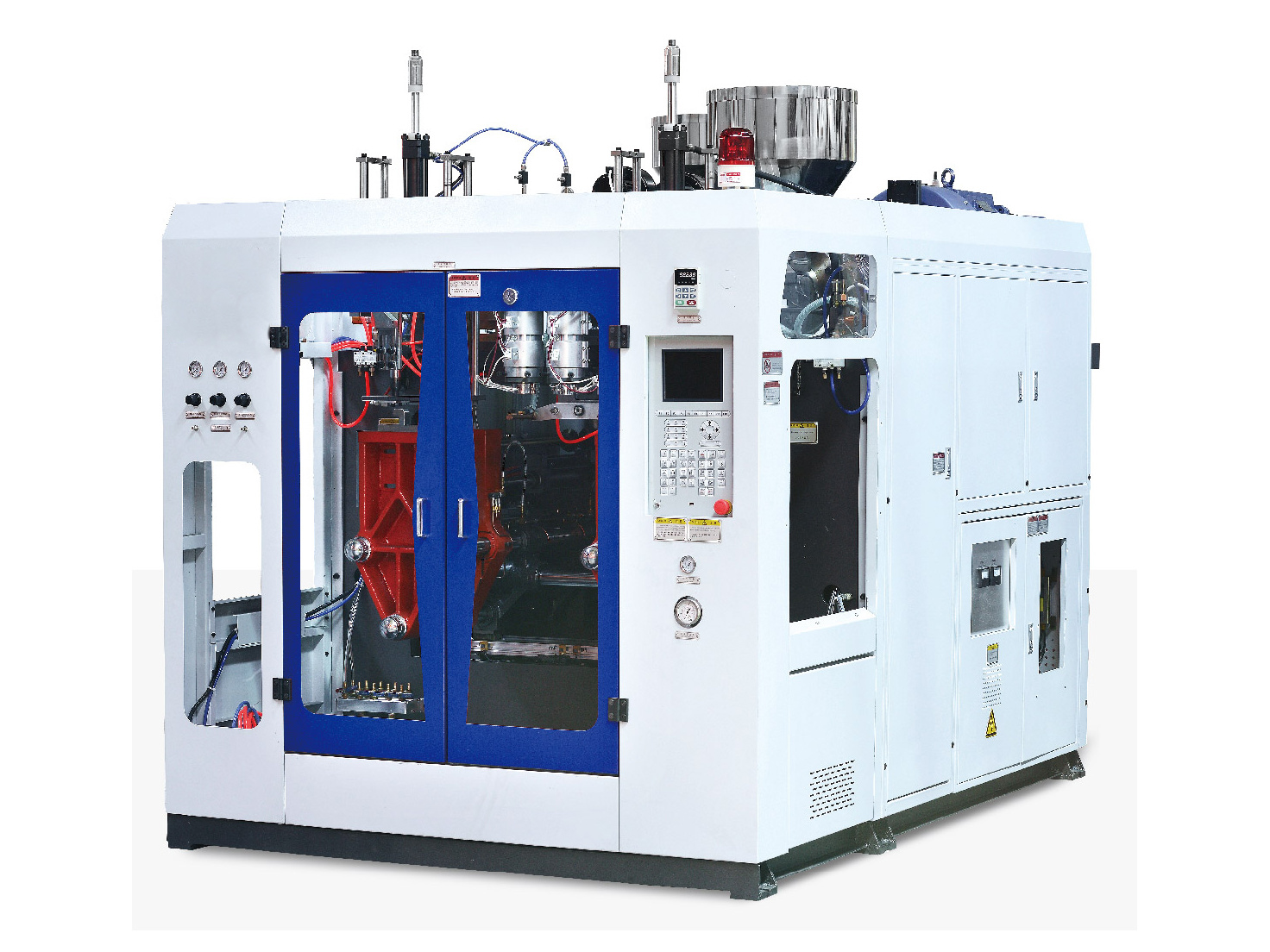
START A CONVERSATION
Tell us what
you are planning
to produce.
Share your product, output and production requirements. Our team will help you find the right configuration.